What Is Engine Cam?
An Engine Cam and different types of Cams are the mechanical components, that rotates in a constrained path and transmit the rotating motion into reciprocating or oscillating motion to another machine or machine tool component known as a Follower, Engine Cam and Follower assemblies are two types of assemblies that function together in any machine element, Because of the line contact between them, cam and followers are examples higher pairs. Some difficult to achieve motions can be readily done by employing different types of Cams and Followers.
A Cam and Follower Mechanism is a patterned form that is installed on a shaft and moves a lever or follower. The mechanism of the combination of Cam and Followers determines the functioning principle of Cam and Followers.
The Cam is the most significant components of the mechanics, which is commonly employed in internal combustion engines to operate intake and exhaust valves, machine tools, and printing control systems, among other things. They are typically made via die casting, milling, and punching. They are are found in wall clocks as well as the feed mechanism of automated lathe machines. They are also found in paper cutting machines and textile weaving machinery.
Also Read:
- What is a Gear – Types of Gears – Their Working – Advantages, And More
- What is a Propeller Shaft – How The Power Transfer From Engine To Drive Axle
Types of Cams
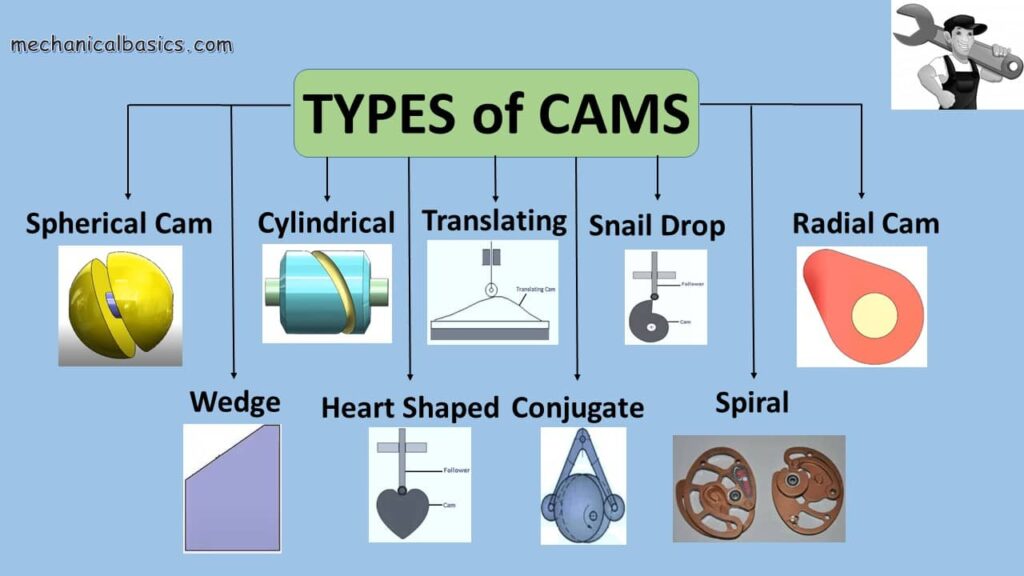
There are different types of Cams according to the application, design, motion, etc. All those works on same working principle but the Design of Cam, Shape of Cam, Size of Cam will be different. The following are some of the most regularly used cams.
- Wedge Cam or Flat Cam
- Radial or Disc Cam
- Cylindrical Cam
- Spiral
- Globoidal
- Conjugate
- Translating
- Snail
- Heart shaped
- Spherical
Wedge Cam
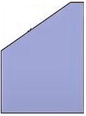
The wedge cam has a translation motion, which has a shape of wedge, but the follower that paired with Wedge Cam can oscillate or translate. The spring is used to keep the cam in touch with the followers. A flat plate is sometimes used in place of a wedge with a groove in which the follower is held and spins; in this grove, a roller follower is employed.
Radial Cam or Disc Cam
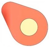
The Radial Cam is one of the important types of cams in the cam family, which is fixed center. The cam is pin-jointed, and the follower spins radially with regard to the cam. The radial cam operation is incredibly small and straightforward.
Cylindrical Cam
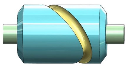
A cylindrical cam rotates in a cylindrical circle about its own axis. It is sometimes referred to as a barrel cam. The follower, which is coupled to the spring, makes contact with the cylindrical cam in two ways.
- In the first scenario, a groove is carved on the barrel’s perimeter, and the follower is restricted into this grove, where it oscillates.
- In the second situation, the cylinder’s end serves as a working surface.
Spiral Cam
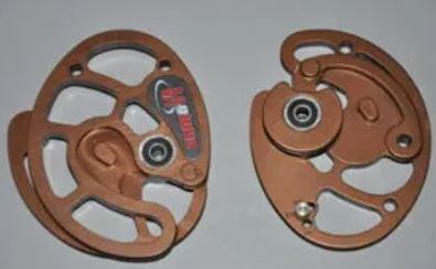
A Spiral Cam is one of the types of cams, mostly used in computer applications. These spiral grooves contain teeth that make contact with a pin gear follower. The movement of the follower is determined by the radial distance of the grooves measured from the cam’s axis.
Globoidal Cam
Globoidal Cam comes in two varieties.
- The First Is a Concave Surface
- The Second Is a Convex Surface.
A circumferential incision is created on the cam’s perimeter to allow the follower to rotate. The operation of convex and concave surfaces is the same, but the applications are different. The follower moves in an oscillating fashion. This type of cam is utilized in medium-speed engines when the follower must travel at a large oscillation angle.
Conjugate Cam
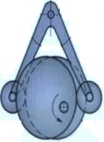
A Conjugate cam is made up of two discs, which is one of the types of cams. These two discs are properly aligned and make contact with the follower. The key advantage of this form of the follower is that it operates silently and has a reduced wear and tear rate when compared to other cams. This cam is the finest of the bunch for high-speed and high-dynamic-load applications.
Heart-Shaped Cam
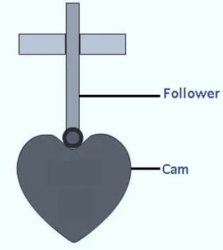
The Heart-Shaped Cam appears to be asymmetrical. It is mostly used to turn a shaft in order to retain a cam in a predetermined position by applying pressure from a roller.
Translating Cam
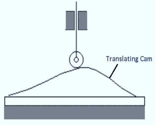
The Translating Cam is made out of a groove or contour plate with an oscillating follower in front of it. The movement of the follower is specified by the groove or contour plate.
Snail Drop Cam
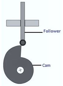
The snail drop cam is used in a mechanical timekeeping clocking-in clock; for example, the daylight advance mechanism can start at exactly midnight and include a follower for more than 24 hours via the cam in a spiral route, which resulted in a sudden cut-off and the follower will descend and begin the day progress.
Spherical Cam
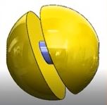
Spherical Cam is another main types of cams mechanism which provide less back-lash and less friction loss.
Types Of Cams Shapes According To The Constraint Of The Follower
It is critical for the cam and follower system to maintain surface contact between the cam profile and the follower at all periods of rotation and motion. In the cam and follower system, spring force, gravitational force, or positive drive are employed to accomplish this. Cams are categorized on this premise based on the sort of follower and are as follows.
- Preloaded Spring Cam
- Positive Drive Cam
Preloaded Spring Cam: The spring force is utilized in this sort of cam. The compression spring is preloaded into the followers in such a way that it is always in contact with the surface.
Positive Drive Cam: This sort of cam requires no external force to operate. The follower is built in such a way that no external force is required.
Cam Mechanism:
The mechanism of the combination of Cam and Follower determines the operating principle of Cam and Follower. As said, Engine Cam is a part of the machine that is a spinning disk or eclipse about the Follower’s minor axis. As a result, Cam is a mechanical device that delivers reciprocating, oscillating, or linear motion to Follower. Cam’s geometry is often an oval, an incomplete circle, or an eclipse. An engineer may visualize the motions that will generate the outer burge, which is periodic to its locus, if he or she studies an oval-shaped Cam. This outer burge is highly beneficial and effective for periodic mechanical tasks. Head Cams are classified into two categories. The first kind is a single head cam, while the second type is a multiple head cam.
The Cam and Follower mechanism is significant in the engineering sector and serves many distinct tasks for various machines.The Cam and Follower Nomenclature consists
- Trace Point
- Base Circle
- Pitch Curve
- Prime Circle
- Cam Profile
- Pressure Angle
- Pitch Point
- Pitch Circle
Let us have a look at these cam and follower nomenclature in detail
Trace Point
A Trace Point is a point on the follower that depicts the movement of the follower. This is the centre of the roller for a roller follower. As a result, the Trace Point is the roller centre, and the follower’s motion will be defined in terms of the roller center’s movements.
If the follower has a flat face, the Trace Point is the point on the face of the follower that is in contact with the cam surface when the follower is in one of the extreme positions; we generally select that extreme—position when the follower is closest to the cam centre.
Base Circle
The base circles are the shortest circles that can be created using the cam centre as a centre and contacting the cam profile. As a result, the radius of the base circle, denoted by Rb, is referred to as the radius of the base circle.
Pitch Curve
We will consider the kinetic inverse while defining the pitch curve. It is a four-link mechanism in the kinetic inverse, with a fixed link using a cam, a roller, and a follower. This link is fixed in four-link mechanism, but in a kinematic chain, if we fix a kinematic inversion holding cam.
The position of the roller’s centre will result in a curve parallel to the cam profile. It is the location of the trace point or roller centre after kinetic inversion with the cam fixed.
Prime Circle
With the cam centre as the centre and tangent to the pitch curve, the smallest circle may be drawn. This circle is tangent to the pitch curve and has its centre on the camshaft axis. This is known as the prime circle.
If Rb is the base circle radius and
Rr is the roller radius, then
then the prime circle radius is Rp = Rb+ Rr
Cam Profile:
It is the region of a cam’s surface where the follower makes contact.
Pressure Angle:
It is generated by the normal to the pitch curve and the follower’s line of motion.
Pitch Point:
The pressure angle is at its peak value at this point.
Pitch Circle:
The circle that crosses through the pitch point is the pitch point.
Also Read:
- Four Stroke Engine – Its Processes – Advantages, Applications – And More
- Two Stroke Engine – Its Processes – Advantages, Applications – And More
Advantages of Engine Cams and Types of Cams:
The advantages of types of cams are
- Bearings always distribute uniformly, regardless of the unit’s arrangement by presence of Cams.
- Cams may provide a broad variety of linear movements.
- They are quite adaptable.
- They will convert the different actions or movements into required movements thus results in working of machine or machine or engine or other else.
Disadvantages of Engine Cam and Types of Cams:
The disadvantages of types of cams are
- There are chances of backlash.
- Costlier to build, and more precise to machine.
- A negative radius of curvature is not possible.
Applications of Engine Cam and Types of Cams:
There are several applications for types of cams, they are as follow
- Types of Cams are frequently employed in I C engines to operate the intake and exhaust valves.
- These are commonly seen in wall clocks.
- These are utilized in the automated lathe machine’s feed mechanism.
- Machines should be screwed.
- Machines for cutting gears.
- This device aids the printing of the screen in printing machinery. The push aids in getting into the position where the printing will take place, and the pull aids in printing on that.
- This is the primary mechanism in hydraulic systems.
- In Textile Types of Machinery, the Cam and Follower Mechanism serves to sew garments by a push and pull to move.
- In that situation, the mechanism is affected by fluid pressure.
- Mechanized machinery, Cam, and Follower are utilized in various sections that are automated in motion.
Conclusion:
The cam and follower mechanism is an important component in the machine and machine tool because it is used to move a small machine component smoothly, which leads to the motion of entire equipment. By combining the cam and follower mechanism, central locks and conventional lock systems are also constructed. Cam and follower mechanisms play an important role in mechanical engineering. As a result, accuracy and patience are necessary to put the mechanism into action. Before comprehending the notion of cam and follower, the user needs first be aware of the linkages and pairings.
As the Cam is a higher pair device, the user should allow the degree of freedom to utilize it in a machine component. Finally, it is advised that the user not raise the pressure angle in order to reduce the possible influence of side thrust.
Frequently Asked Questions
What are the cam types based on follower movement?
Following are the classifications of cam based on the follower movement.
- Rise-Return-Rise (R-R-R) cams
- Dwell-Rise-Return-Dwell (D-R-R-D) cams
- Dwell-Rise-Dwell-Return-Dwell (D-R-D-R-D) cams
- Dwell-Rise-Dwell (D-R-D) cams.
Describe undercutting in cam. How does it happen?
The cam profile must be a straight line with no loops. If the pitch curve’s curvature is too sharp, a portion of the cam shape is lost, and the intended cam motion is not achieved. A cam of this type is said to be undercut. Undercutting happens as a result of attempting to get a high follower lift with a little cam rotation.
What are the main components of a cam mechanism?
The driving part is referred to as the cam. The driven component is termed as the follower. The frame is what holds the cam in place and guides the follower.