What is Oldham Coupling?
The Oldham Coupling is a type of mechanical mechanism and Inversion of Double Slider Crank Chain that consists of pairs, and linkages, which combine results in mechanical movement. A Double Slider Crank Chain consists of two sliding pairs and two turning pairs whereas; the Single Slider Crank Chain consists of only one sliding pair and three turning pairs. Therefore, as a double slider crank chain inversion type, the Oldham Coupling Mechanism does consist of two sliding and turning pairs.

In some mechanical applications, the transmission of rotary motion from one shaft (let say link) to another shaft is not possible, due to its non-coaxial parallel aligned axis but, their axis still be parallel to each other. So, Oldham Coupling is used to connect the two shafts, which is used to transfer the rotary motion of one shaft to another shaft, which is parallel to each other.
Also Read:
- Whitworth Quick Return Mechanism – Parts, Construction, Working, Advantages, Disadvantages, Applications – FAQ’s
- Crank And Slotted Lever Mechanism – Parts, Construction, Working, Advantages, Disadvantages, Applications – FAQ’s
Construction and Working of Oldham Coupling:
Construction of Oldham Coupling:
The Oldham Coupling consists of 2 turning and 2 sliding pairs, which is applicable only when two shafts are parallel in alignment. A typical Oldham Coupling Mechanism consists
- Supporting Frame (let Link 2)
- Driving Shaft
- Driven Shaft
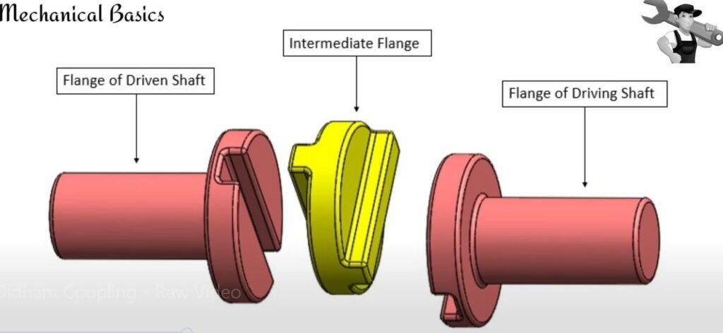
- Flange 1 (let Link 1) / Driver Flange
- Flange 2 (let Link 3) / Driven Flange
- Intermediate/Central/Connecting Flange (let Link 4)
The Supporting Frame also indicates as Link 2. Supporting Frames are the legs where the whole setup or whole Oldham Coupling Mechanism is constructed. It will observe the vibrations that develop while working or rotating of coupling. The Driving Shaft is the main shaft that acts as a source to the whole mechanism. Besides, the Driven Shaft is another shaft that is connected to the driver shaft; additionally, it runs or works with the help of driver shaft.
Also Read:
- Propeller Shaft – Universal Joint, Uses, Working, Advantages, Disadvantages, Applications
- Casting Process – Types, Manufacturing Process, Advantages, Disadvantages, Applications – FAQ’s
Flange 1 and Flange 2 are the sphere-type flat rib or collars that are attached to the end of the shaft to increase the strength to transform the energy from one shaft. It does consist of diagonal deep grooves to fit into other parts. Generally, these flanges are manufactured by metals like Aluminum or Stainless Steel to possess less weight and high performance.
The Intermediate Flange or Central Piece or Connecting Flange is a part that acts as an intermediate to attach the Flange 1 and Flange 2 for transferring the energy. The outer side diagonal structure on both sides of the intermediate flange is called a Tongue, which further fix into the deep grooves of Flange 1 and Flange 2 on either side. Then to make sure the bond between the intermediate flange and Flange 1, Flange 2 is strong, a small lock pin is used. Whereas, the Intermediate or Central or Connecting Flange is manufactured by Plastic or Fabric Material to withstand deformation and resist the Electrical Shocks.
Working of Oldham Coupling:
The working of Oldham Coupling Mechanism is simple alike its construction. The Driving shaft will be rotated using any external source, which further rotates the Flange 1, intermediate flange, Flange 2, and Driven Shaft parallelly.

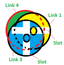
As the driver shaft rotates, Flange 1 or Link 1 rotates at an angle. Due to this, the tongue of the intermediate flange (side 1) or Link 4 will slide in the flange 1 or link 1 groove, which results in a rotating motion of the Intermediate Flange with the same angle that Flange 1 rotates.

Similarly, the tongue of the intermediate flange (side 2) will slide in between the groove of Flange 2 or Link 3 and results in the rotation of Driven Shaft with the same angle that Intermediate Flange or Link 4 rotates. Therefore, we can say that links 1, 3, and 4 will rotate with the same angular velocity.
Maximum Sliding Speed of Tongue:
If the distance between the axis of the two shafts remains constant through the process, then the center of the Intermediate Flange or Piece will develop an imaginary Circle, in which the diameter of the circle is equal to the distance between the two shafts (driver shaft and driven shaft). Therefore, the maximum Sliding Speed of Each Tongue of Oldham Coupling in meters per second can be taken as

Advantages of Oldham Coupling:
The Advantages of Oldham Coupling Mechanism are
- It can transmit the energy between non-coaxial parallel shafts.
- The Oldham Mechanism produces low restorative force on the bearings of driver and driven shafts.
- The small Oldham Couplings do even operate at high speeds.
- The Intermediate Flange or Central Piece of Oldham Coupling is electrical resistance.
- The Oldham Mechanism consists low moment of inertia.
- The rotating speed of driver and driven shaft is same.
- The Oldham Coupling Mechanism is Economical compared to other types of couplings.
Disadvantages of Oldham Coupling:
The Disadvantages of the Oldham Coupling Mechanism are
- Compared to other types of couplings, the Oldham Coupling Mechanism develops low maximum speed, which vary around 3000 rpm.
- Oldham Coupling Mechanism is not suitable for large angular displacements.
- Oldham Coupling develops low torque and stiffness.
- The Axial Reaction at maximum torques will be taken by Bearings instead of Coupling.
Applications of Oldham Coupling:
The Applications of Oldham Coupling are
- Oldham Mechanism is used in Stepper motor driven positioning stage
- Oldham Coupling Mechanism is used in Robotics and Servos.
- Uses at Motion controller with zero reaction performance
- Oldham Mechanism is used in damping system vibrations and accommodating alignments.
Conclusion:
The Oldham Coupling Mechanism is one of the inversions of Double Crank Slider Chain Mechanism, which is being one of the necessary couplings in small applications. Nowadays, robotics, servo motors, etc., are depending on it. Transformation of sliding movement into turning movement is quite difficult in most cases, which is further possible by only Oldham Mechanism.
Frequently Asked Questions:
What is a Flange?
The Flange is a Sphere Type Collar or Flat Rim type object or component that is used to perform any mechanical operation. Moreover, it increases the strength of the binding.
What is Intermediate Flange?
The Intermediate Flange is a collar or flat rim that acts as a connector of Flange 1 or Link 1 and Flange 2 or Link 3 in the Oldham Coupling. An Intermediate Flange consists of two Tongues on either side of it. So, it can slide in deep grooves for movement.
What is a Coupling?
Coupling is a type of attachment of two or more objects, combine increases the strength of the whole equipment and is further used for sliding or rotating purposes.
What is Turning Pair?
The combination of two elements is called a Pair. The relative moment of such pair or two elements resulting in pure turning is called Turning Pair. If a shaft is attached with Collar or Flange, further the rotation of the shaft results in rotation of flange then the relative movement or turning of both shaft and flange is called as Turning movement.
What is Sliding Pair?
The combination of two elements is called a Pair. The relative moment of such pair or two elements resulting in pure sliding motion is called a Sliding Pair.