What is Vapour Compression Refrigeration Cycle?
Vapour Compression Refrigeration Cycle (or Vapor Compression Cycle) is a type of Refrigeration Cycle, ideal cycle for the Refrigeration System which can be found in Vapour Compression Refrigeration Device (or Vapor Compression Refrigeration Device). In the Vapour Compression Cycle or Vapour Compression Refrigeration Cycle, the refrigerant undergoes segment changes, is one of the numerous refrigeration cycles and the maximum drastically habituated device for air- exertion of systems and motorcars.
It is extensively utilized in Air Conditioning, Natural Gas Plants, Petroleum Refineries, Petrochemical Plants, Homes, Marketable Refrigerators, Huge-Scale Storages for stupefied or frozen storehouse of ingredients and flesh, cooled exchanges and street buses, and a bunch of different marketable and synthetic services. Generally, the Refrigeration is the process of removing the heat from the space and adding or rejecting it to the atmosphere. The devices that provide cooling effect is called as Air Conditioners, Refrigerators, Cold Storages, etc.
Also Read:
- Refrigeration Cycle – Types, Parts, Working, Advantages, Disadvantages, Applications – FAQ’s
- Otto Cycle – Process, Parts, Working, Advantages, Disadvantages, Applications – FAQ’s
Table of Contents
Construction and Working of Vapour Compression Refrigeration Cycle:
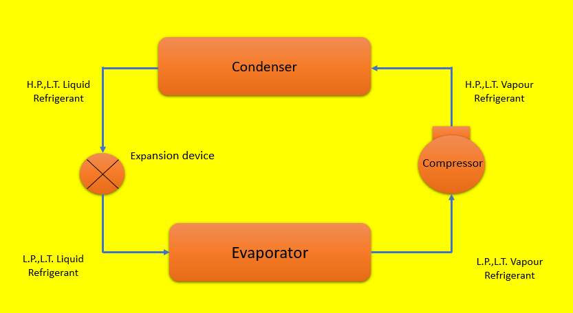
Vapour Compression Cycle (or Vapor Compression Refrigeration System) is a Refrigerant Cycle where an appropriate running substance, nominated as refrigerant is used. It has 4 basic and main components rudiments. They are
- Compressor
- Condenser
- Growth valve (or Expansion Valve) and
- Evaporator
Vapour Compression Refrigeration System (or Vapor Compression Refrigeration System) is the maximum considerably used Refrigerant Cycle in any type of application we use. Let us read about these Vapor Compression Refrigeration System Components in detail
Compressor
- The Function of Compressor in Vapour Compression Refrigeration System (or Vapor Compression Refrigeration System) is to compress low strain, low temperature Vapour Refrigerant (or Vapor Refrigerant) to transform it into excessive strain, excessive temperature of Vapour Refrigerant.
- The low-pressure, low temperature vapour refrigerant from Evaporator is drawn into compressor through inlet or suction valve, where it is compressed to high pressure and high temperature.
- The high pressure and high temperature vapour refrigerant are discharged into the Condenser through delivery or suction valve.
Condenser
- The Function of Condenser in Vapour Compression Refrigeration System (or Vapor Compression Refrigeration System) is to give a heat transfer surface, through which the heat passes from the Hot Vapour Refrigerant to the condensing medium like atmospheric air.
- While passing through the condenser coil, the high pressure and high temperature vapour refrigerant gives up its ideal heat to the girding condensing medium (which is generally air or water) and gets converted it into high pressure, low temperature, liquid refrigerant, which leaves the Condenser and enters into Expansion Device or Expansion Valve.
Expansion Device (or Expansion Valve)
- The Function of Expansion Device (or Expansion valve) in Vapour Compression Refrigeration System (or Vapor Compression Refrigeration System) is to reducethe pressure of liquid refrigerant entering the Evaporator, so that, liquid refrigerant will vapourized at a veritably low temperature in the Evaporator by absorbing ideal heat from the substance or space to be cooled.
- Thus, the Refrigerant can absorb heat from the substance or space to be cooled in the evaporator at the low temperature.
Evaporator
- The Function of Evaporator in Vapour Compression Refrigeration System (or Vapor Compression Refrigeration System) is to give a heat transfer face, through which, the heat can pass from the cooled space to the liquid refrigerant flowing through the Evaporator coils and thereby vaporizing the liquid refrigerant.
- Evaporator consists of wounded coils or pipes in which, the flowing fluid that is (liquid refrigerant at low temperature and low pressure) absorb its ideal heat of vaporization from the space to be cooled and gets faded to Vapour Refrigerant. Due to the junking of heat that is (immersion of heat) by refrigerant, the needed space gets cold producing chilling effect.
In addition to the four top Vapour Compression Refrigeration System Components, there are other bias that are similar as receiver and strainer-drier assembly may be handed for safety consideration as well as for perfecting the COP of the System.
Receiver
TheFunction of Receiver is to give a constant supply of liquid refrigerator to evaporator as demanded.
Strainer – Drier Assembly
- The Function of Strainer-Drier Assembly in Vapour Compression Refrigeration System (or Vapor Compression Refrigeration System) is to remove contamination from the refrigeration system.
- The common form of strainer is a fine mesh screen made up of metal, which traps the contaminants, pollutants and foreign patches from the system.
- The strainer can be washed of and refitted or it can be replaced by new one.
Drier
- The Function of Drier in Vapour Compression Cycle (or Vapor Compression Refrigeration System) is to remove humidity (i.e. water vapour associated with refrigerant) from refrigeration system.
- The Drying Agent may be Silica-Gel, Actuated Alumina or Zeolite (Molecular Sieve).
- It is located in the Liquid Line ahead of Expansion Valve.
Types of Vapour Compression Refrigeration Cycle
The main types of Vapour Compression Refrigeration Cycle (Vapor Compression Refrigeration Cycle) with explanation, their representation on P-h and T-S diagrams are
- Dry Compression: Cycle with dry saturated vapour refrigerant at inlet of compression and saturated vapour after compression (i.e. outlet of compression).
- Wet Compression: Cycle with wet vapour refrigerant at inlet of compressor and dry saturated vapour refrigerant at outlet of compressor.
- Cycle with Superheating of Vapour Refrigerant (Vapor Refrigerant): Located before the Refrigerant enters the Compressor
- Cycle with Undercooling or Sub-Cooling of Liquid Refrigerant: Located before the Refrigerant enters the Expansion Valve.
Also Read:
- Diesel Cycle – Process, Working, Advantages, Disadvantages, Applications – FAQ’s
- Difference Between COP and Efficiency
Dry Compression in Vapour Compression Refrigeration System
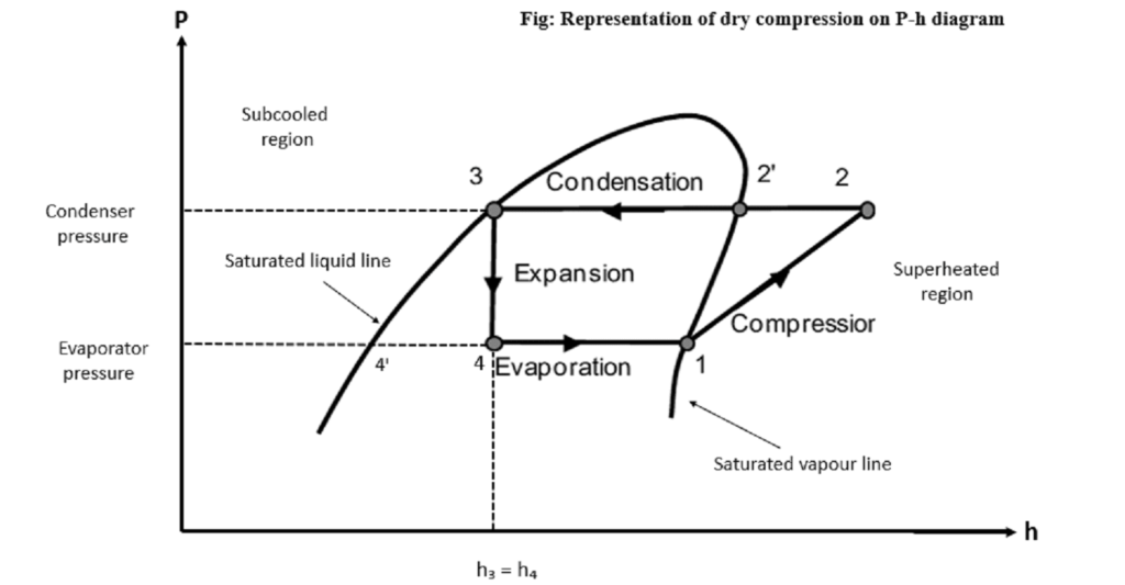
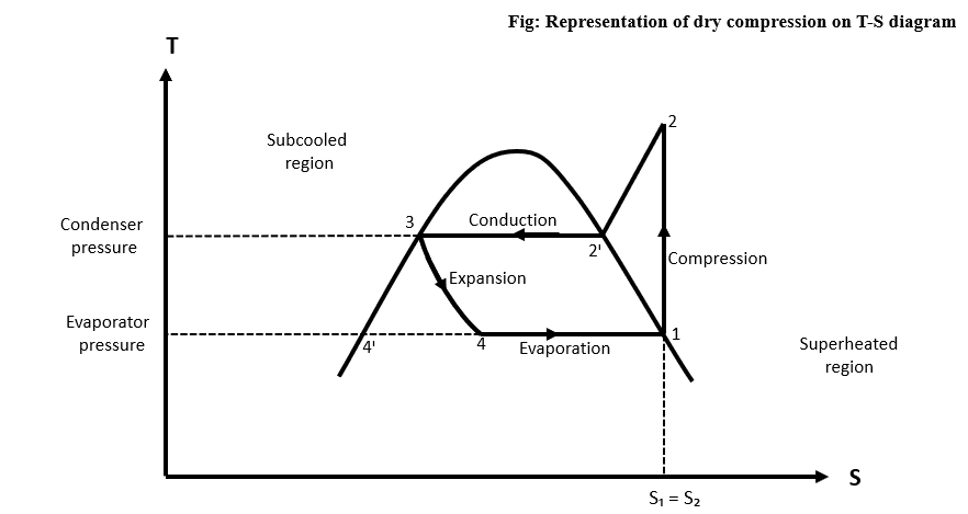
- For maximum Refrigerating Effect, the absorption/extraction of heat during evaporation process is continued till the Vapour Refrigerant (Vapor Refrigerant) becomes Dry Saturated or Slightly Superheated.
- Then, the entire compression will take place in superheated region and is known as Dry Compression.
- The Dry Saturated Vapour Refrigerant (Vapor Refrigerant) entering the compressor at point (1) is compressed Isentropically to point (2), which increases the pressure from Evaporator pressure to Condenser pressure.
- At point (2), the Superheated Vapour Refrigerant enters the Condenser, where it rejects the heat to atmosphere at Constant Pressure. Due to rejection of sensible heat, the temperature of Vapour Refrigerant decreases from superheat temperature T2 to saturation temperature Tי2 then, the change of phase takes place at constant temperature i.e. latent heat is removed during process 2ᶦ – 3 and reaches to liquid saturation temperature point (3).
- Then this liquid refrigerant is passes through Expansion Valve, where it is throttled (expanded) keeping the Enthalpy constant and reducing the pressure. Due to Throttling, some heat is evolved and the part of liquid refrigerant gets evaporated. Therefore, we get liquid- vapour mixture of refrigerant (i.e. wet vapour refrigerant) at the outlet of Expansion Valve.
- This Wet Vapour Refrigerant (or Wet Vapor Refrigerant) enters into Evaporator at point (4), where it absorbs latent heat during process 4-1 and gets converted into Dry Saturated Vapour Refrigerant and cycle is completed.
Calculation of C.O.P of Dry Compression
- The Co-Efficient of Performance (COP) of Dry Compression Vapour Compression Refrigeration System can be taken as following
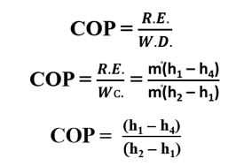
- Refrigerating effect of Vapour Compression Refrigeration System is taken as

- Compressor Work is taken as

Where, m֯ is the mass of refrigerant circulated per minute or per second
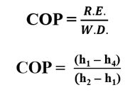
- COP of Vapour Compression Refrigeration System (or Vapor Compression Refrigeration System) is given by,
In the above formula, the notation h1, h2, h4 are the enthalpies at respective points. Enthalpy of refrigeration after compression can be calculated as,
h2 = h2י + Cp (T2 – T2י)
Where Cp = specific heat of vapour refrigerant
Wet Compression of Vapour Compression Refrigeration System
- If the condition or state of refrigerant at the inlet of compressor is wet vapour refrigerant and this refrigerant undergoes compression, then such a type of compression is called as Wet Compression.
- If the vapour refrigerant contains some liquid particles of refrigerant, it is called a Wet Vapour Refrigerant (or Vapor Refrigerant). In other words, the wet vapour refrigerant is not completely dry. This happens due to incomplete evaporation of liquid refrigerant in Evaporator.
- Wet compression is not desirable, because,
- Liquid droplets present in the refrigerant enters the Compressor and may damage the valve and moving parts of compressor.
- Droplets of liquid refrigerant will strike over the piston causing the damage to the piston.
- The liquid refrigerant will damage cylinder head and the valves, thus causing mechanical damage to the Compressor. The liquid refrigerant may wash out the lubricating oil or lubricant from the walls of cylinder causing wear and tear.
- Moreover, the liquid droplets of refrigerant would mix with the lubricating oil. The oil then passes to condenser and adversely affects the heat transfer rate.
Wet Compression with Compressor Discharge as “Dry Saturated Vapour”
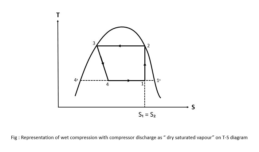
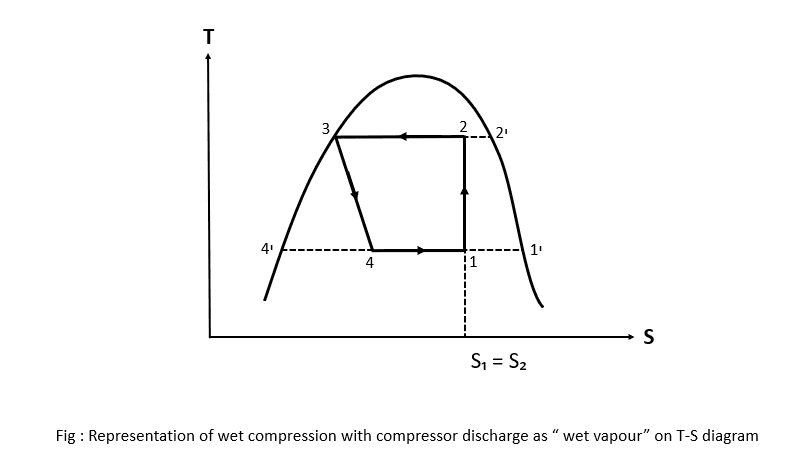
COP formula for both the condition (a) and (b) are same. So, It is given as
Superheating
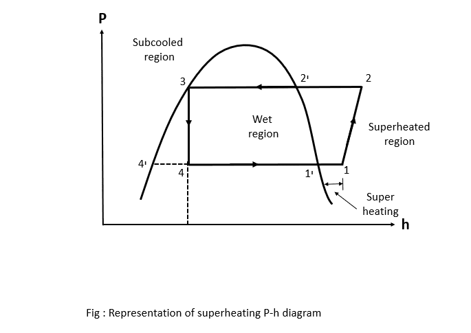
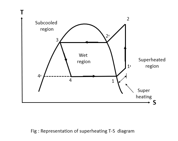
- Superheating is defined as, “the process of allowing vapour refrigerant to stay for some more times in evaporator, so that, it absorbs more heat and comes out of evaporator in superheated form”.
- A Vapour Compression Cycle with Superheated Vapour at the inlet of compressor is shown on P-h and T-S diagrams.
- In this cycle, heat is absorbed or extracted in two stages, firstly, from point 4 to point 1ᶦ (latent heat) and secondly, from point 1ᶦ to point 1 (sensible heat). The remaining cycle is the same. It is explained below.
- Evaporation of liquid refrigeration starts at point 4 and continue up to point 1ᶦ, where refrigerant becomes dry saturated vapour refrigerant and then this vapour refrigerant is superheated before entering the compressor (i.e. at inlet of compressor represented by point 1). The process of superheating is represented by process 1 – 1ᶦ.
Sub-Cooling or Undercooling

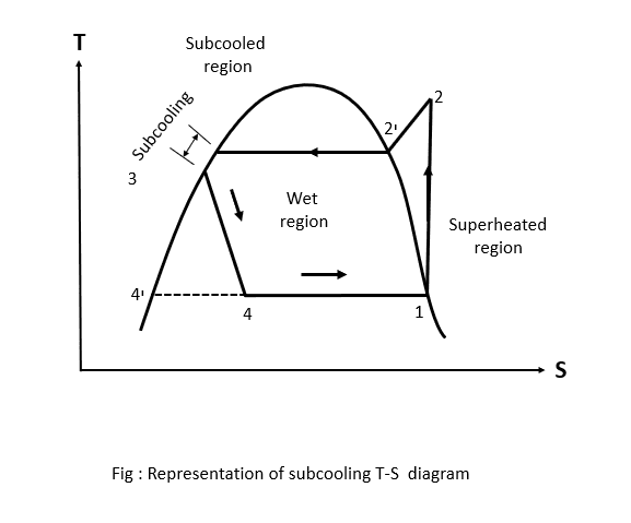
- Sub-Cooling or Undercooling is defined as the process of cooling the refrigerant below condenser temperature for given pressure.
- After undergoing cooling and condensation process (2-3ᶦ), the liquid refrigerant is further cooled below the condenser temperature (i.e. Saturation temperature) up to temperature T3 along liquid line before the start of compression process.
- Such a process is also called as undercooling of refrigeration and is generally done along the liquid line. Refer T-S diagram shown below, where subcooling or undercooling is represented by curve 3-3ᶦ along saturated liquid line or curve.
Advantages of Vapour Compression Refrigeration cycle
The Advantages of Vapour Compression Refrigeration System (or Vapor Compression Refrigeration System) are
- C.O.P (Co-Efficient of Performance) of Vapour Compression Refrigeration Cycle is Relatively high because, its working cycle act nearly to reverse Carnot cycle
- The size is low for given Capacity of refrigeration.
- Running Cost of Vapour compression Refrigeration Cycle is less.
- Vapour compression refrigeration system is available in various size and capacities with easy control.
- It can be employed over higher number of temperatures.
Disadvantages of Vapour Compression Refrigeration cycle
The Disadvantages of Vapour Compression Refrigeration System (or Vapor Compression Refrigeration System) are
- Leakage of refrigerant in Vapour Compression Refrigeration Cycle is the major problem.
- Higher initial investment cost is required.
- High Cost of Refrigerants in Vapour Compression Refrigeration Cycle is one of the disadvantages.
Application of Vapour Compression Refrigeration Cycle
The applications of Vapour Compression Refrigeration System (or Vapor Compression Refrigeration System) are
- It is used in Water Cooler Devices.
- The Vapour Compression Refrigeration System is also used in Cold Storage Houses.
- Moreover, it is used in Domestic Refrigerator, Air Conditioning applications.
- We can found Vapour Compression Refrigeration System even in Ice Factory.
Conclusion
The Vapor Compression Refrigeration System is always a reverse cycle for the Thermal Cycles because in the cycles like Otto Cycle, Diesel Cycle, etc. the heat is taken by the system and work is done but in the Refrigeration System, the heat is rejected by the system and work is done.
Frequently Asked Questions
Which refrigerants are utilized in Vapour Compression Cycle?
Ans. The maximum not unusual place consists of ammonia, Freon and different chlorofluorocarbon refrigerants, CFCs and HFC-134a (a non-poisonous hydrofluorocarbon). Now-a-days Freon Refrigerants like R-11 and R-12 are banned, due to the fact their use is that the most motive behind ozone layer depletion.
In Vapour Compression Refrigeration Cycle, why is enlargement done in a throttling valve and now no longer in enlargement engine?
Ans. In Vapour Compression Refrigeration Cycle, throttling gadgets is used for the technique of enlargement. The technique of throttling is Iso-Enthalpy this is enthalpy stays regular. In addition to the present, performance of throttling enlargement is greater compared to different kind of enlargement technique. In an enlargement engine enlargement technique is preferably isentropic; because of friction, the enlargement follows a Poly-tropic behavior.
Therefore, the performance of enlargement is less. Due to friction there may be additionally drop in enthalpy for the duration of enlargement technique. In easy phrases enthalpy of refrigerant lower for the duration of enlargement technique, which isn’t always desirable, because it lowers COP. Therefore, isenthalpic technique (regular enthalpy technique) is favored. That is why, a throttle valve or a capillary tube is favored than an enlargement engine in Vapour Compression Refrigeration System.
Why is oil introduced to Vapour Compression Refrigeration System?
Ans. Even though the refrigerant is the running fluid required for cooling, the lubricant or oil is required for lubrication of the compressor. Oil minimizes the friction between mechanical parts. Oil additionally keeps a seal among the excessive and coffee facet of the compressor.
What happens if a refrigerant garage tank is overfilled?
Ans. Overfilled garage packing containers can also additionally explode due to liquid refrigerant increasing while heated. Transportation of refrigerant garage cylinders greater than 80% can be a DOT violation.
Which is the most secure refrigerant?
Ans. Refrigerants are identified using index numbers, on what their capability impact on international warming and ozone depletion. Ammonia is poisonous and flammable, however while utilized in structures designed with present day technology, it’s far a secure refrigerant to use.
Why R134a is hired as refrigerant?
Ans. R134a has pretty exact dielectric houses because it has excessive thermal stability, low boiling point, and chemical inertness towards the development substances used; and is non-poisonous and non-flammable. A dielectric substance in its gaseous country may be used to save electric powered discharges.